
KIAA's reference pipeline assembles parsed CAD, BIM and document layers into a queryable knowledge graph deployable across construction, industrial and manufacturing environments through configuration, not custom code.
Building a knowledge graph from engineering data is not primarily a storage or tooling problem it is an orchestration problem. Once CAD layers, IFC models, PDFs and technical specifications have been parsed and normalized (as covered in Part 1), the challenge shifts to assembling those outputs into a coherent, versioned, queryable graph that survives project handovers, revision cycles and organizational change.
KIAA's reference pipeline addresses this in six repeatable stages: ingestion and normalization, geometric and design-feature extraction, ontology alignment and semantic classification, text-to-graph integration for specifications and reports, knowledge graph materialization with built-in quality controls, and finally the exposure of differentiated knowledge layers geometric, functional, lifecycle and risk to downstream consumers.
What distinguishes an accelerator from a custom build is not the sophistication of any single component but the reusability of the whole. Layer-to-class mappings, ontology extensions, SHACL validation rules and ML classifiers are all stored as configuration artifacts, not embedded in project-specific scripts. New projects inherit 70–80% of the pipeline unchanged and specialize only the domain vocabulary and naming conventions that differ.
This Part also demonstrates how the same accelerator core serves three distinct industry contexts engineering and industrial facilities (P&IDs, control logic, HAZOP), construction and the built environment (IFC-centric BIM, project controls, FM handover) and manufacturing and product design (3D model repositories, PLM integration, design-feature reuse) and closes with a practical onboarding path for teams ready to operationalize KIAA in their own environment.
Building on the parsing techniques above, a practical KIAA pipeline for CAD, BIM and documents generally follows a repeatable pattern. The accelerator provides the infrastructure and reference components; you customize configurations and mappings.

The pipeline begins with ingestion into a neutral representation:
This stage standardizes coordinates, units, layer encodings and entity IDs to allow consistent processing across projects and formats.
Using the normalized model, the pipeline derives higher‑level features:
Recent work demonstrates that such feature graphs can serve as the basis for knowledge graphs and even graph neural network models for design analytics and recommendation.
The accelerator ships with a set of ontologies and classification models; you specialize them by configuration rather than code.
Typical mechanisms:
1. Rule‑based mapping
2. Ontology mapping
3. ML‑assisted classification
Because these mappings are described as rules, ontological constraints and model configurations, they can be adapted per client or project without altering the core accelerator.
4. Integrating specs, procedures and reports
The next layer links text documents to graph entities:
In a KIAA pipeline, extracted entities (equipment IDs, drawing numbers, procedure codes, material designations) are resolved against the graph to attach documents and clauses to specific assets, locations or failure modes.
Example relations:
Now queries like “show all assets whose inspection procedures changed after revision C of Spec 10-001” become simple graph traversals.
5. Knowledge graph materialization and quality controls
Once entities and relations are resolved, the accelerator materializes them into a graph database or RDF store. BIM and construction research often uses RDF/OWL with SPARQL, while PLM and product design commonly use property graph databases both patterns are supported.
Quality control mechanisms include:
Because these controls are part of the accelerator, you can apply them across projects with minimal adaptation.
6. Knowledge layers for different stakeholders
The final outcome is not a single monolithic graph but a set of knowledge layers tailored to different concerns:
KIAA exposes these as APIs and query templates so that digital twin dashboards, analytics pipelines and AI copilots can consume them without knowing CAD or BIM internals.
It is tempting to see “CAD to knowledge graph” as a one‑off integration or data science project. The downside of that approach is that each project re‑implements the same ingestion, mapping and validation patterns with slightly different code and libraries.
A KIAA accelerator takes a different stance:
1. Configuration over code
2. Domain packs, not bespoke schemas
3. Reference implementations validated by research and industry
In practice, this means your teams focus on what constitutes knowledge in your domain not on building extract‑transform‑load plumbing or low‑level CAD parsers.
While engineering, construction and manufacturing differ substantially in their artifacts and constraints, KIAA leverages recurring patterns in how knowledge is structured.
A KIAA accelerator in this context emphasizes piping, instrumentation, control systems and hazard analysis ontologies.
Ontology‑driven, bidirectional workflows mapping IFC to knowledge graphs and back are well established in research, which KIAA can reuse as templates.
Here, KIAA focuses on design feature ontologies, product structure, process planning and integration with PLM and MES systems for closed‑loop manufacturing intelligence.
Despite these differences, the accelerator’s core remains the same: ingestion, feature extraction, ontology alignment, text integration and graph materialization.
To make the accelerator flavor more concrete, consider how a KIAA pipeline might map CAD layers into a knowledge graph using configuration rather than code.
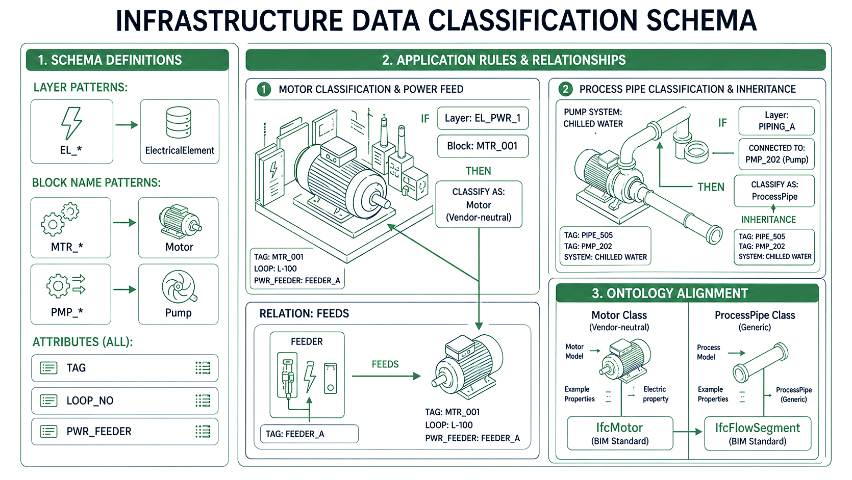
1. Layer schema
2. Rules
3. Ontology alignment
All of these rules live in KIAA's configuration and ontology layer. Adding a new project or discipline may mean defining new patterns and classes, but the mapping engine, graph infrastructure and QA stack remain unchanged. Critically, this configuration layer is also how a firm captures and scales the expertise of its senior engineers across the entire organization the naming conventions, classification logic and validation thresholds that an experienced discipline lead would apply instinctively are codified once as rules and applied automatically to every project thereafter.
A junior CAD technician's work is therefore automatically aligned with the company's established best practices and quality standards at the point of ingestion, without requiring manual review gates or tribal knowledge transfer for every new team member or project
Operationalizing this approach typically follows a repeatable, accelerator‑centric path:
Because KIAA is accelerator‑driven, each iteration strengthens a reusable foundation rather than creating another siloed solution. Over time, your engineering drawings, specifications and reports converge into a set of structured knowledge layers that can power digital twins, AI copilots and advanced analytics across engineering, construction and manufacturing.
The deeper value, however, is the Digital Thread a continuous, auditable flow of engineering information that KIAA maintains from the first design specification through procurement, construction and commissioning to the final as‑built condition. Every change, deviation and decision is traceable back to the requirement that motivated it and forward to the asset that implements it, giving organizations not just a knowledge graph but a living record of engineering intent that survives project handovers, team changes and system upgrades.
The engineering organizations that will lead the next decade are not necessarily those with the most data they are those that can make their accumulated drawings, specifications and models speak to each other. KIAA closes the gap between geometry and meaning, between a file repository and a living knowledge base, between tribal expertise locked in individual engineers and institutional intelligence that survives every handover and team change.
The six-stage reference pipeline presented here is not a theoretical framework; it is a configurable, research-validated accelerator that transforms the way construction, industrial and manufacturing organizations build, operate and maintain complex engineered assets. By codifying naming conventions, classification logic and validation thresholds as reusable ontological artifacts, KIAA ensures that senior engineering judgment is applied automatically and consistently not just on one project, but across every project thereafter.
The deeper outcome is the Digital Thread: a continuous, auditable flow of engineering intent from the first design specification through procurement, construction and commissioning to the final as-built condition. Every requirement is traceable to the asset it governs. Every design decision links back to the constraint that motivated it. This is not just better data management it is a structural competitive advantage for any organization serious about AI-ready engineering intelligence.