
Engineering organizations hold decades of CAD and BIM data rich in geometry but poor in semantic meaning. KIAA lifts these files into queryable knowledge graphs, resolving inconsistent naming conventions and unlocking cross-project intelligence.
Engineering organizations in construction and manufacturing are sitting on decades of drawings, CAD models, specifications and reports that encode critical "tribal knowledge" about assets, processes and constraints. Yet the real problem is not storage or retrieval it is semantic debt. DWG and IFC files are technically sophisticated: they carry geometry, topology, parametric feature trees and rich design feature information (DFI) accumulated over project lifecycles. Geometry, in other words, is largely a solved problem. Semantic intent is not.
What remains unresolved is the meaning layer above the geometry. A wall in IFC is a solid with dimensions; whether it is a fire-rated partition, a structural shear wall or a temporary works element is encoded if at all in free-text attributes, layer names or block conventions that differ across every firm, project and discipline. There is no enforced standard for layer naming in DWG. One firm labels structural beams as STR_BEAM, another uses S-BEAM, and a third buries them in a generic A-STRUCT layer. This lack of standardized layer conventions is not just an inconvenience it makes cross-project analytics nearly impossible without a deliberate semantic lifting step that normalizes intent across heterogeneous sources.
A KIAA‑style accelerator addresses precisely this gap. Rather than treating CAD and BIM files as geometry containers to be viewed or exported, it treats them as structured inputs to a configurable knowledge graph pipeline one that lifts raw geometric entities into typed, interlinked knowledge nodes with stable identifiers, queryable relationships and traceable provenance.
Instead of building yet another custom integration, KIAA provides reusable ontologies, configurable mapping recipes and semantic extraction toolchains that can be adapted to the layer conventions, naming standards and domain vocabulary of any engineering, construction or manufacturing environment.
Traditional CAD and BIM tooling was designed primarily for geometry and drawing production, not for explicit, queryable semantics. Product Lifecycle Management (PLM) and PDM systems largely follow this paradigm by managing CAD files and related documents, not the knowledge embedded in them.
At the same time, studies in mechanical and product design show that CAD models contain design feature information (DFI) parameters, feature trees, constraints and modeling logic that could be used for design reuse, quality analysis and manufacturing integration if lifted into knowledge graphs.
In practice, this requires robust, reusable parsing techniques for CAD/BIM files, PDFs and technical specifications that can populate AI‑ready knowledge layers instead of ad‑hoc project scripts.
On the documentation side, engineering organizations maintain vast repositories of technical manuals, process sheets and test reports whose content is often duplicated or inconsistent, making it hard for engineers to discover the right information at the right abstraction level.
This is the context in which a KIAA accelerator operates: it is not “just another data lake,” but a set of building blocks that systematically convert these artifacts into layered, machine‑navigable knowledge.
Crucially, it reconnects the engineering logic behind a design decision why a particular tolerance, weld detail or material grade was chosen by linking the drawing, its CAD layers and feature geometry to the surrounding technical reports, calculations and specifications, turning previously disconnected silos into a single, queryable engineering knowledge graph.
In this context, KIAA is best understood as a Knowledge Integration and Intelligence Accelerator rather than a single product or a bespoke project. It provides a configurable reference architecture and implementation toolkit that you can adapt to your own ecosystems, ontologies and toolchains.
A typical KIAA accelerator for engineering, construction and manufacturing includes:
1. Pre‑defined domain ontologies and schema templates
2. Multi‑format ingestion connectors
3. Semantic extraction recipes and mapping rules
4. Operational scaffolding
Because these pieces are pre‑built and configurable, you are not “developing a custom platform from scratch”; you are instantiating and extending an accelerator to your data, standards and naming conventions.
The hardest part is not building another graph store; it is extracting reliable semantics from messy, heterogeneous CAD and BIM data.
The core engineering hurdle is the spatial–semantic gap: a line on a PIPING layer might be a pipe, but its true function is only understood when you resolve its topological relationships ; for example, that it is connected to a specific pump, belongs to a particular process system and crosses a governed zone.
Several well‑documented challenges around these spatial and semantic dependencies show repeatedly in real projects and in the research literature.
Layer names and colors often encode discipline‑specific conventions that vary across projects, companies and even individuals.
Research in BIM and IFC demonstrates that semantic interoperability issues persist even when using open standards, because different parties interpret and populate schemas differently.
CAD entities (lines, solids, surfaces) are inherently geometric; their function (pipe, cable tray, crane rail, safety barrier) is often implicit in layer names, blocks, or parametric relationships rather than attached as explicit metadata.
Papers on design feature information show that extracting function requires analyzing parametric feature trees, constraints and topological relationships to reconstruct higher‑level design intent.
KIAA builds on this by not just reading static geometry but traversing the parametric feature tree and associated constraints to infer what each object is supposed to do within the larger system architecture for example, distinguishing a machined hole used for alignment from one used for fluid flow, or separating a cosmetic fillet from a stress‑relief feature that drives downstream manufacturing and maintenance decisions
CAD drawings for plants, buildings or complex machines frequently rely on nested blocks and external references:
To build a coherent knowledge graph, you must resolve all references, normalize instance identifiers and propagate semantics across these nested contexts, as seen in IFC‑to‑knowledge‑graph workflows and digital twin platforms.
In a KIAA pipeline this is implemented as recursive XRef and block resolution combined with identifier normalization, so that a given asset tag appearing inside an external reference is treated as the same logical entity as the tag in the master equipment schedule or P&ID, rather than as a separate node. This prevents duplicate or orphaned assets in the knowledge graph and ensures that downstream queries and analytics operate on a single, consistent representation of each engineered object.
Meaningful queries often cross scales and disciplines: “Which electrical feeders supply all HVAC units in zone B?” or “Which weld procedure applies to this beam connection?”
Digital twin knowledge graph work shows that linking building geometry (IFC), schedules and process information requires a carefully designed ontology and alignment strategy, typically using stable identifiers such as IFC GUIDs or asset tags. In practice, linking electrical, mechanical and structural layers also demands a shared coordinate system and a robust alignment ontology so that elements from different models truly occupy the same physical space.
KIAA treats this as a data reconciliation problem: it maintains a unified asset registry that reconciles the design model with as‑built laser scans and field changes, so discrepancies are captured as explicit deltas instead of silently generating duplicate or misaligned assets in the knowledge graph.
Engineering reality is versioned: drawings are revised, as‑built conditions diverge from design, and temporary works come and go.
Knowledge graph approaches in BIM stress the need for version handling and bidirectional workflows that allow updated graphs to regenerate standards‑compliant IFC or CAD artifacts, so that the graph does not drift from the contractual model.
A KIAA accelerator must provide abstractions and patterns to handle these challenges in a reusable way, instead of baking project‑specific logic into code.
To make KIAA useful for downstream AI and analytics, it must implement repeatable, technology‑agnostic normalization pipelines that turn CAD/BIM files, PDFs and technical specifications into neutral knowledge layers.
The first step is to strip away vendor‑specific formatting, proprietary metadata and file‑level quirks so that DWG, IFC, STEP and PDF inputs all converge on a common intermediate schema for elements, geometry, relationships and identifiers.
This is the stage where domain‑specific knowledge is codified into machine‑readable logic through ontologies, mapping rules and validation constraints, so that downstream AI and analytics never see raw files only consistent, schema‑aligned knowledge layers that can be reused across projects instead of rebuilt with bespoke scripts
For CAD and BIM, the parsing stack typically combines vendor‑neutral SDKs and semantic conversion toolkits
1. DWG/DXF and DGN
The pseudo code below is high‑level (no vendor lock‑in) but shows how the accelerator would iterate DWG entities and emit neutral objects.
// Pseudo-code DWG adapter using an ODA-style API

Database db = HostApplicationServices.WorkingDatabase;

db.ReadDwgFile("plant-model.dwg", FileShare.Read, true, "");

using (Transaction tr = db.TransactionManager.StartTransaction())

{

    BlockTable bt = (BlockTable)tr.GetObject(db.BlockTableId, OpenMode.ForRead);

    BlockTableRecord ms = (BlockTableRecord)tr.GetObject(bt[BlockTableRecord.ModelSpace], OpenMode.ForRead);


    foreach (ObjectId id in ms)

    {

        Entity ent = tr.GetObject(id, OpenMode.ForRead) as Entity;

        if (ent == null) continue;


        string layerName = ent.Layer;

        string typeName  = ent.GetType().Name; // Line, Polyline, BlockReference, etc.


        // Send into neutral CAD element DTO for the accelerator

        Console.WriteLine($"{typeName} on layer {layerName}");

    }

    tr.Commit();

}
IFC (BIM)
The code below are illustrative, not production‑grade, and they reinforce the “accelerator with configurable pipelines” story.
#Minimal IFC adapter using IfcOpenShell

import ifcopenshell


def load_ifc_model(path: str):

model = ifcopenshell.open(path)

print(f"IFC schema: {model.schema}")          # e.g. IFC4

return model

def iter_elements(model, ifc_type: str):

"""Yield basic info for all entities of a given IFC type."""

for inst in model.by_type(ifc_type):

info = inst.get_info()

yield {

"global_id": info.get("GlobalId"),

"name": info.get("Name"),

"type": inst.is_a(),

}

if name == "main":

model = load_ifc_model("project.ifc")

for wall in iter_elements(model, "IfcWall"):

print(wall)
STEP and mechanical models
From KIAA’s perspective, these format‑specific adapters all emit into the same intermediate schema:
This intermediate schema is what later becomes the geometric and functional knowledge layers, independent of whether the source was DWG, IFC or STEP.
Engineering organizations still rely heavily on PDFs for drawing sheets, vendor datasheets and legacy documentation. The parsing pipeline must handle both true PDFs (vector content) and scanned PDFs (raster images).
A typical KIAA‑aligned PDF pipeline includes:
1. Structure and layout analysis
2. Table and schedule extraction
3. OCR and raster handling
By standardizing these steps, KIAA produces drawing‑sheet knowledge layers (title blocks, legends, schedules, notes) that attach to geometric layers from CAD/BIM, bridging human‑readable drawings with machine‑navigable graphs.
The below code makes the PDF parsing pipeline tangible: text + tables converted into structured objects for mapping to graph entities.
import pdfplumber

import pandas as pd


def extract_title_block_and_tables(pdf_path: str):

    with pdfplumber.open(pdf_path) as pdf:

        for page in pdf.pages:

            # 1) Extract raw text for notes / general clauses

            text = page.extract_text() or ""


            # 2) Extract all tables (BOMs, equipment lists, cable schedules)

            for table in page.extract_tables():

                df = pd.DataFrame(table[1:], columns=table[0])

                yield {

                    "page_number": page.page_number,

                    "raw_text": text,

                    "table": df,

                }


for item in extract_title_block_and_tables("PFD-101.pdf"):

print(item["page_number"], item["table"].head()) Technical specifications, method statements and test reports are predominantly textual and require NLP‑centric pipelines to convert into constraints, requirements and evidential links.
Research on knowledge graph extraction from text and patents emphasizes the need for robust named entity recognition (NER), relation extraction and triple construction to build useful engineering knowledge graphs.
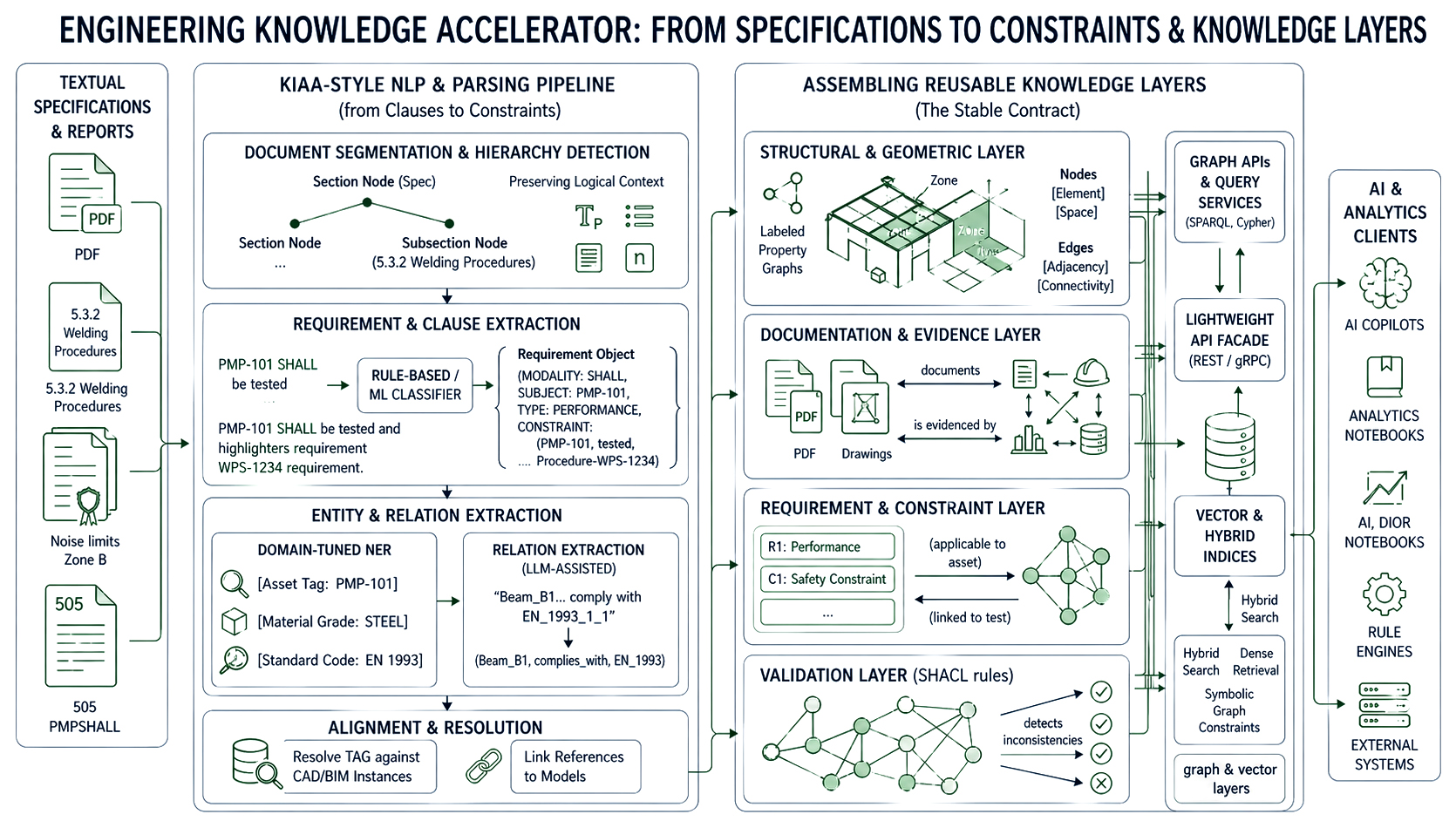
A KIAA‑style pipeline for specs and reports generally includes:
1. Document segmentation and hierarchy detection
2. Requirement and clause extraction
3. Entity and relation extraction
All extracted entities and relations are then aligned with the existing asset and geometry layers: tags are resolved against CAD/BIM instances, drawing references are linked to models, and procedure IDs are connected to processes.
The code below concretely shows how the accelerator can turn free text into requirement objects for the constraint layer.
import spacy

from typing import Dict, List


nlp = spacy.load("en_core_web_lg")  # in practice, domain-tuned model


REQUIREMENT_MARKERS = {"shall", "must", "shall not", "must not"}


def extract_requirements(text: str) -> List[Dict]:

    doc = nlp(text)

    requirements = []


    for sent in doc.sents:

        lower = sent.text.lower()

        if any(marker in lower for marker in REQUIREMENT_MARKERS):

            requirements.append({

                "text": sent.text.strip(),

                "start_char": sent.start_char,

                "end_char": sent.end_char,

            })

    return requirements


spec_text = open("spec_section_5_3.txt").read()

for req in extract_requirements(spec_text):

print(req["text"]) All three pipelines CAD/BIM, PDF/drawings, and text specs ultimately emit into a set of normalized knowledge layers that downstream AI and analytics can treat as stable contracts:
1. Structural and geometric layer
The following illustrates how parsed assets and extracted requirements are materialized as RDF triples within a KIAA pipeline, using a standard vocabulary and stable identifiers that downstream tools can reliably reference:
from rdflib import Graph, Namespace, URIRef, Literal

from rdflib.namespace import RDF, RDFS


EX = Namespace("https://example.com/kiaa#")


def asset_uri(tag: str) -> URIRef:

    return EX[f"Asset/{tag}"]


def requirement_uri(idx: int) -> URIRef:

    return EX[f"Requirement/{idx}"]


g = Graph()

g.bind("ex", EX)


# Example: link a pump asset to a requirement extracted from the spec

pump_tag = "P-101"

req_text = "Pump P-101 shall be designed for 10 barg minimum discharge pressure."


pump = asset_uri(pump_tag)

req = requirement_uri(1)


g.add((pump, RDF.type, EX.Pump))

g.add((pump, EX.hasRequirement, req))

g.add((req, RDF.type, EX.Requirement))

g.add((req, RDFS.comment, Literal(req_text)))


print(g.serialize(format="turtle"))
Because `asset_uri()` and `requirement_uri()` are deterministic functions driven by stable tag identifiers, any downstream system SPARQL endpoint, AI copilot, BI tool can reliably dereference the same node regardless of which pipeline run produced it.
1. Documentation and evidence layer
2. Requirement and constraint layer
1. Graph APIs and query services
In most KIAA deployments, these graph and vector layers are not accessed directly by downstream tools, but through a thin REST or gRPC facade.
A lightweight API layer standardizes how AI copilots, analytics notebooks and external systems query assets, requirements and evidence without needing to know the underlying graph engine or query language.
from fastapi import FastAPI

from rdflib import Graph


app = FastAPI()

graph = Graph().parse("kiaa_graph.ttl", format="turtle")


@app.get("/assets/{tag}")

def get_asset(tag: str):

    q = f"""

    PREFIX ex: <https://example.com/kiaa#>

    SELECT ?p ?o WHERE {{

      ex:Asset/{tag} ?p ?o .

    }}

    """

    res = graph.query(q)

    return [{"predicate": str(row.p), "object": str(row.o)} for row in res]
Validation rules (e.g., SHACL) can be run directly against these graphs to detect inconsistencies or missing data before AI models consume them.
2. Vector and hybrid indices
Because all parsing and mapping logic is implemented as configurable components in the accelerator, new projects or domains typically require only adjustments to adapters (e.g., new title block templates), NLP models (e.g., additional entity types) and ontology mappings not new code paths.
The result is a set of reusable engineering knowledge layers that AI and analytics pipelines can reliably consume across engineering, construction and manufacturing scenarios.
Engineering organizations do not lack data they lack a structured way to make it mean something. The three parsing pipelines explored in this part CAD/BIM adapters, PDF drawing extractors and NLP-driven spec parsers each address a distinct layer of the semantic debt problem. Together, they converge on a shared intermediate schema: typed entities, stable identifiers, queryable relationships and traceable provenance.
This is the foundation KIAA is built on. Rather than replacing existing CAD or BIM tooling, it sits above it lifting raw geometric and textual artifacts into normalized knowledge layers that AI, analytics and digital twin platforms can reliably consume.
In Part 2, we walk through the end-to-end reference pipeline that assembles these layers into a production-grade knowledge graph, explore cross-industry deployment patterns and show how rule-driven ontology mapping makes the accelerator reusable not just repeatable.